Wiring Diagram For APC
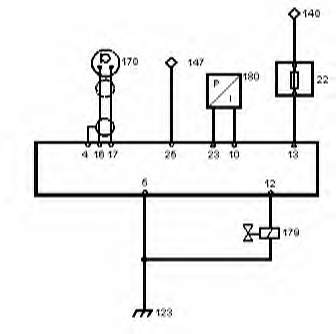
System:
![]()
 Components:
![]() 148:Power from +/15 terminal on ignition coil.
148:Power from +/15 terminal on ignition coil.
![]() 22: Fuse (10 amp)
22: Fuse (10 amp)
![]() 147: Ignition Coil Terminal -/1.
147: Ignition Coil Terminal -/1.
![]() 178: Knock Sensor.
178: Knock Sensor.
![]() 179: Solenoid Valve.
179: Solenoid Valve.
![]() 180: Pressure Transmitter
180: Pressure Transmitter
![]() 123: Ground for solenoid and control unit.
123: Ground for solenoid and control unit.
Wiring the APC is simple. Only 9 pins are necessary.
The numbers for the pins can be seen on the back side of the control unit plug once the top cover is removed. There will be several wires not used for this installation, they can be removed. I will soon have a picture of the plug itself and how to remove the individual connectors.
Wire Conectors:
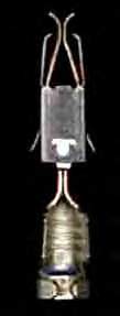
The wire connectors for the ECM are available from Saab (Part Number: 91 20 957). You will need at least 9 of them, I would recommend getting a few spares just in case you mess one up. They require a special crimping tool available from most tool dealers. Be sure to crimp them properly or you will get a bad connection!!
|
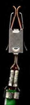 Good Crimp! YES! |
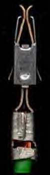 Bad Crimp! NO! |
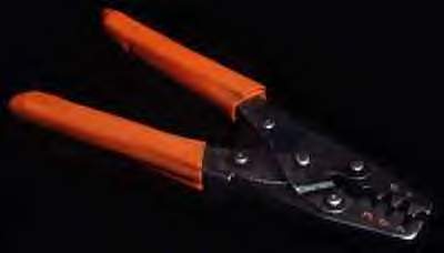
Below in a picture of the crimping tool you will need to get for the factory wire connectors. The ones shown are Mac brand, however Snap-On and most other professional tool companies make the same thing.
**Special Notes:
![]()
![]() If you're installing APC on a
car with a ballast resistor, do not take the power from the coil + terminal.
Instead, find a suitable +12v power supply that is switched on and off with the
ignition.
If you're installing APC on a
car with a ballast resistor, do not take the power from the coil + terminal.
Instead, find a suitable +12v power supply that is switched on and off with the
ignition.